Building an interface board
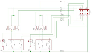
First thing I did was etching a board for two of the encoders because they wouldn't fit well on my prototyping board. I created an eagle library for the part (download) and etched the board which holds the two encoders, two status LED and connects to the mainboard using a 5x2 pin header:
I created the part using the dimensions from the datasheet. It's my first DIY eagle library, so please bear with me if there are some design flaws. It worked fine with my circuit here. Maybe there is some way to make the enclosure pins connect to the GND net. Warning: I used the enclosure as a bridge in my design below.
The schematic. The encoder datasheet contains an application test circuit which shows these resistors with 10k. I also used 10k to drive my PIC portpins.
Below is the board in theory and my toner transfer mask (mirrored!).
I zipped the eagle schematic, board, part library and the etching mask: Download
The finished board, done using Toner transfer and Fe3-Chloride etchant. As you can see, the groundplate is pretty bad. This was my second board ever (after the pic burner board) and this time I heated the toner too few. Also I forgot to mirror the image before printing, so my pin header is different from the schematic. Everything works though ;)
Understanding the encoder output
Second hurdle was to understand how these things output the rotation information. Although there were some examples on the web, I didn't get it until I started from the graph in the datasheet and went tried to write the code for myself. This is the graph from the datasheet:
So, if the two Signal lines are connected to two port pins, I have two bits to read and work with. Only the order of the bit-changes give me the information about turning direction. To see these signals, I connected two LED between each signal line and ground. When turning clockwise, I got 00, then 01, 11, 10, then 00 again. Turning the other way gives 00, 10, 11, 01, 00.
When turning right, the first (right) bit changes after 00 and 11. When turning left, the second (left) bit changes after 00 and 11.
After some trial and error and too many cups of coffee, I had a working code and I was glad having tried it myself. Without this fiddling I'd have never understood the logic behind this.
Testing code
For output, I put the PWM code from last time into a function "void updatepwm(int dutycycle)" and increase or decrease the duty cycle value when turning the knob.
The encoder outputs are connected to RB[0:1].
#include <p18cxxx.h>
#include <p18f2550.h>
#include <delays.h>

//Pin Reset Configurations
#pragma config PBADEN = OFF            //RB0 through RB4 pins are configured as digital I/O on Reset

//Oscillator Settings
#pragma config PWRT = ON               //Soft Power-Up
#pragma config FOSC = HSPLL_HS         //HS oscillator, PLL enabled, HS used by USB
#pragma config PLLDIV = 5              //PLL prescaler divides by 5 (20 MHz oscillator input)
#pragma config CPUDIV = OSC1_PLL2      //CPU @PLL/2=48MHz

//Features
#pragma config MCLRE = ON              //MCLR pin enabled; RE3 digital input disabled
#pragma config LVP = OFF               //Single-Supply ICSP disabled, free RB5
#pragma config DEBUG = OFF             //Background debugger disabled, RB6 and RB7 configured as I/O pins
#pragma config WDT = OFF               //HW Disabled - SW Controlled
#pragma config BOR = OFF               //Brown-out Reset disabled in hardware and software
#pragma config STVREN = ON             //Stack overflow/full reset

void init (void);
void main (void);
void updatepwm (int dutycycle);

void main (void)
{
    char laststate = 0;
    char currentstate = 0;
    int brightness = 512;

    init();
    updatepwm(brightness);

    while(1){

        //check button on rb2
        if (!(PORTB & 0x04))    //buttonA pulls rb2 to ground
        {
            updatepwm(0);
            brightness = 0;
        } else if (!(PORTB & 0x08))    //buttonB pulls rb3 to ground
        {
            updatepwm(1023);
            brightness = 1023;
        } else
        {
            currentstate = PORTB & 0x03;    //read current encoder input

            //check if encoder input has changed
            if (currentstate != laststate)
            {
                //check if first bit changed
                if ((currentstate & 0x01) != (laststate & 0x01))
                {
                    //if both bits were the same before, we're turning right
                    if ((laststate == 0) || (laststate == 3))    //laststate is 00 or 11
                    {
                        brightness = brightness + 16;
                    } else
                    {
                        brightness = brightness - 16;
                    }
                } else {    //second bit changed
                    //now if both bits were the same before, we're turning left
                    if ((laststate == 0) || (laststate == 3))
                    {
                        brightness = brightness - 16;
                    } else
                    {
                        brightness = brightness + 16;
                    }
                }
            if (brightness < 0) {brightness = 0;}
            if (brightness > 1023) {brightness = 1023;}

            updatepwm(brightness);
            laststate = currentstate;
            }
        }
    }
}

//dutycycle must be a value between 0 and 1023
//see http://h3po-notes.blogspot.com/2009/09/using-hardware-pwm-on-pic18f.html
void updatepwm (int dutycycle)
{
    CCPR1L = dutycycle >> 2;
    CCP1CON = 12 | ((dutycycle << 4) & ~12);
}

void init (void)
{
    //setting up pwm
    TRISC &= ~0x04;        //setup rc2 for ccp1
    CCP1CON = 0x0C;        //0b00XX1100 for single mode pwm
                           //XX are bits [0:1] of the 10bit duty cycle value
    CCPR1L = 0x00;         //reset pwm duty cycle
    PR2 = 0xFF;            //pwm period = 750kHz / 256 ~= 2930Hz
    T2CON = 0x07;          //enable, prescale 1:16 => tmr0 counting at 750kHz

    TRISB |= 0x03;         //rb[0:1] quadrature encoder signals
    INTCON2 |= 0x80;       //disable PORTB pullups
}
Phew.


Keine Kommentare:
Kommentar veröffentlichen